Automatic Temperature Controlled Fan Using Arduino
In this arduino based project, we are going to control DC fan speed according to the room temperature and show these parameter changes on a 16×2 LCD display. It is accomplished by the data communications between Arduino, LCD, DHT11 sensor Module and DC fan that is controlled by using PWM.
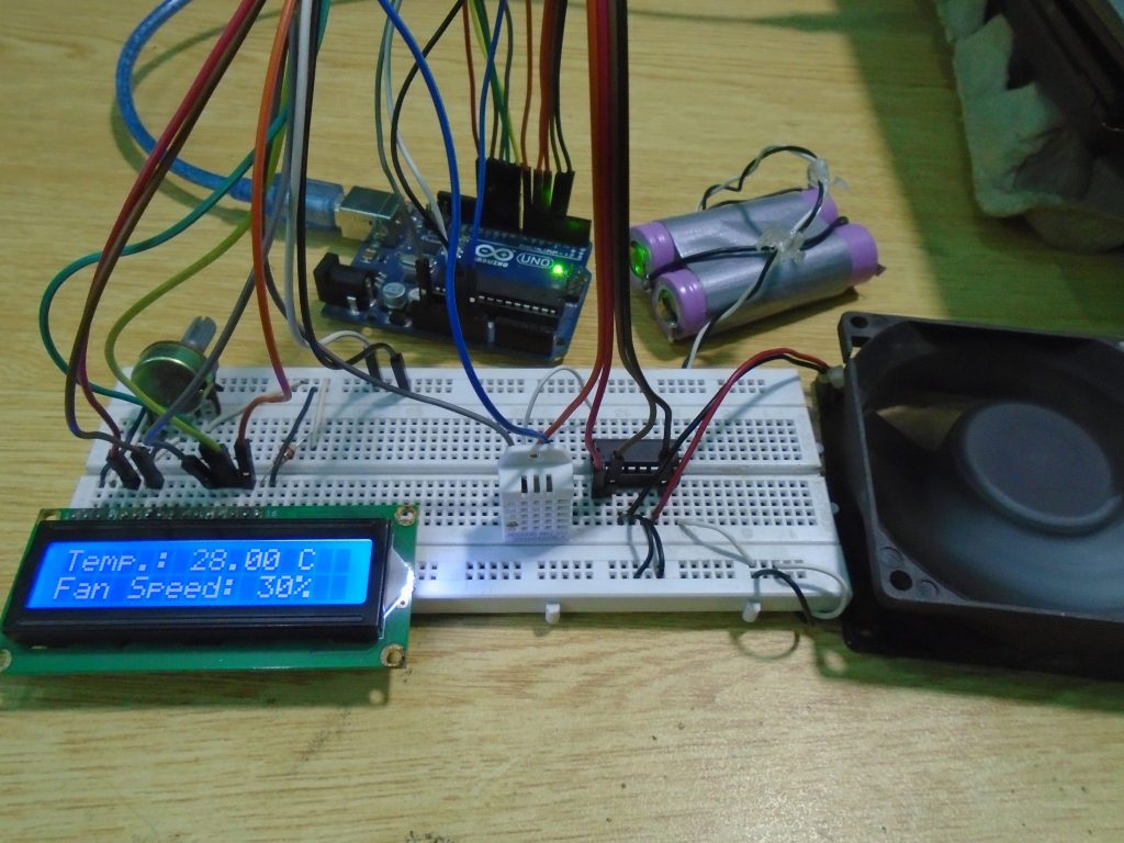
Hey guys again:) In this project i have tried to explain how to built Temperature Controlled FAN with an Arduino. Basically i have used transistor in order to. Temperature Controlled Fan using Arduino. Pins of LCD namely RS, EN, D4, D5, D6 and D7 are connected to arduino digital pin number 7, 6, 5, 4, 3 and 2. And a DHT11 sensor module is also connected to digital pin 12 of arduino. Digital pin 9 is used for controlling fan speed trough transistor.
PWM is a technique by using which we can control voltage. Circuit Components • Arduino UNO • DHT11 sensor • DC Fan • 2n2222 transistor • 9 volt battery • 16×2 LCD • 1K resistor • Connecting wires This project consists of three sections. One senses the temp erature by using humidity and temperature sensor namely DHT11.
Second section reads the dht11 sensor module’s output and extracts temperature value into a suitable number in Celsiu s scale and control the fan speed by using PWM. And last part of system shows humidity and temperature on LCD and Fan driver. Here in this project we have used a sensor module namely DHT11 that are already have discuss our previous project namely “”. Here we have only used this DHT sensor for sensing temperature, and then programmed our arduino according to the requirements. What is PWM? PWM is a technique by using we can control the voltage or power.
To understand it more simply, if you are applying 5 volt for driving a motor then motor will moving with some speed, now if we reduces applied voltage by 2 means we apply 3 volt to motor then motor speed also decreases. This concept is used in the project to control the voltage using PWM. (To understand more about PWM, check this circuit: ) The main game of PWM is digital pulse with some duty cycle and this duty cycle is responsible for controlling the speed or voltage. Suppose we have a pule with duty cycle 50% that means it will give half of voltage that we apply. Formula for duty cycle given below: Duty Cycle= Ton/T Where T= total time or Ton+Toff And Ton= On time of pulse (means 1 ) And Toff= Off time of pulse (means 0) Read More.
Temperature Based Fan Speed Control And Monitoring Using Arduino Day by day, there are different types of intelligent systems are introduced with the improvement in technology. Everything is getting more intelligible and stylish.
There is a growth in the demand of cutting edge technology and also smart electronic systems. In the proposed systems, in the smart systems development. Microcontrollers have become an essential part in the present technologies that are being presented daily. This article discusses temperature based fan speed control and using an Arduino system.This system is used to control the cooling system automatically based on the room temperature. The system uses an Arduino board to implement a control system. Since this system is proposed to control the cooling system and it is very important to know Arduino controlled system well.
Temperature Based Fan Speed Control The temperature-based fan speed control system can be done by using an Arduino board. Now Arduino board is very progressive among all electronic circuits, thus we employed Arduino board for fan speed control.The proposed system is designed to detect the temperature of the room and send that information to the Arduino board. Then the Arduino board executes the contrast of current temperature and set temperature based on the inbuilt program of the Arduino. The outcome obtained from the operation is given through the o/p port of an Arduino board to the LCD display of related data. The generated pulses from the board which is further fed to the driver circuit to get the preferred output to the fan.
Block Diagram of Temperature Based Fan Speed Control The block diagram of the, LCD, Transformer, voltage regulator, High-speed DC motor, temperature sensor, Keil compiler and Assembly or embedded c language. Arduino based Automatic Temperature Controlled Fan Speed Regulator Block Diagram Power Supply A power supply circuit is an electrical circuit used to supply the electrical energy to different electrical loads. The main function of this is to change one form of electrical energy to another load. Sometimes these are stated to as electric power converters. There are different types of power supplies are available.
Write something about yourself. No need to be fancy, just an overview. No Archives Categories. Provided by Scott Web Service LLC Scott Web Service of Wisconsin Statistics Report: sws-wis.com Summary Period: December 2016 - Referrer Generated 03-Jan-2017 00:17 EST. Pozdraviteljnie konverti s dnem rozhdeniya dlya deneg raspechatatj 3.